Wednesday, May 26, 2010

Tutorial : FLUENT - SIMULATING A MIXING ELBOW (2D)


This tutorial is further process from Tutorial : GAMBIT - MODELING A MIXING ELBOW . This tutorial illustrates the setup and solution of the two-dimensional turbulent fluid flow and heat transfer in a mixing junction. The mixing elbow configuration is encountered in piping systems in power plants and process industries.

It is often important to predict the flow field and temperature field in the neighborhood of the mixing region in order to properly design the location of inlet pipes.In this tutorial you will learn how to:

• Read an existing grid file into FLUENT
• Use mixed units to define the geometry and fluid properties
• Set material properties and boundary conditions for a turbulent forced convection problem
• Initiate the calculation with residual plotting
• Calculate a solution using the segregated solver
• Examine the flow and temperature fields using graphics
• Enable the second-order discretization scheme for improved prediction of temperature
• Adapt the grid based on the temperature gradient to further improve the
prediction of temperature

Related Posts:
- Tutorial : GAMBIT - MODELING A MIXING ELBOW (2D)

DOWNLOAD TUTORIAL:
FLUENT TUT01.PDF


Another Reading :
Computational Fluid Dynamics: Fluent, Inc., Computational Fluid Dynamics, Muscl Scheme, Flux Limiter, Lattice Boltzmann Methods

A study in computational fluid dynamics for application to the understanding of commercial software

The trends in CFD are continuous, dynamic, and real: a variety of new computational fluid dynamics (CFD) software packages are just a mouse click away ... article from: Automotive Design & Production

Investigating the potential use of natural ventilation in new building designs in Turkey [An article from: Energy & Buildings]Computational Fluid Dynamics: A Practical Approach
Read More ..

Thursday, May 20, 2010

Tutorial : GAMBIT - MODELING A COMBUSTION CHAMBER (3-D)


In this tutorial, you will create the geometry for a burner using a top-down geometry construction method in GAMBIT (creating a volume using solids). You will then mesh the burner geometry with an unstructured hexahedral mesh.

In this tutorial you will learn how to:
• Move a volume
• Subtract one volume from another
• Shade a volume
• Intersect two volumes
• Blend the edges of a volume
• Create a volume using the sweep face option
• Prepare the mesh to be read into FLUENT 5/6 

In this tutorial, you will create a combustion chamber geometry using the “top-down” construction method. You will create volumes (in this case, bricks and cylinders) and use Boolean operations to unite, intersect, and subtract these volumes to obtain the basic geometry. Finally, using the “blend” command, you will round off some edges to complete the geometry creation.

For this model, it is not possible to simply pick the geometry and mesh the entire domain with hexahedral elements, because the Cooper tool (which you will be using in this tutorial) requires two groups of faces, one group topologically parallel to a sweep path, and the other group topologically perpendicular. However, the rounded (blended) edges fit in neither group. See the GAMBIT Modeling Guide for a more detailed description of the Cooper tool. You need to decompose the geometry into portions that can be meshed using the Cooper tool. There are several ways to decompose geometry in GAMBIT. In this example, you will use a method whereby portions of the volume around the blend are split off from the main volume.

The problem to be considered is shown schematically in Figure above. The geometry consists of a simplified fuel injection nozzle that feeds into a combustion chamber. You will only model one quarter of the burner geometry in this tutorial, because of the symmetry of the geometry. The nozzle consists of two concentric pipes with radii of 4 units and 10 units respectively. The edges of the combustion chamber are blended on the wall next to the nozzle.

DOWNLOAD TUTORIAL
TUTORIAL GAMBIT 04


- Experimental studies of incineration in a cylindrical combustion chamber
- Design Engineering Challenges and Solutions of Kistler Automotive Combustion Pressure Sensors, Water-cooled Sensors, Piezoelectric Sensors, the Crank Angle ... System, and the Sensor Calibrarion Process
- Fuels of Opportunity: Characteristics and Uses in Combustion Systems

Combustion Science and Engineering (Computational Mechanics and Applied Analysis)Combustion, Fourth Edition
Read More ..

Friday, May 7, 2010

Journal & Publication about Training, Research, Isotopes, General Atomics (TRIGA) Reactors


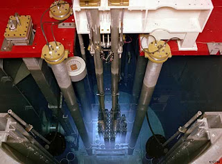
The TRIGA was developed to be a reactor that was designed to be "safe even in the hands of a young graduate student." GA's reactors are used in many diverse applications, including production of radioisotopes for medicine and industry, treatment of tumors, nondestructive testing, basic research on the properties of matter, and for education and training.

TRIGA is a class of small nuclear reactor designed and manufactured by General Atomics. GA's TRIGA reactor is the most widely used non-power nuclear reactor in the world. GA has sold 66 TRIGA reactors, which are in use or under construction at universities, government and industrial laboratories, and medical centers in 24 countries.

Edward Teller headed a group of young nuclear physicists in San Diego in the summer of 1956 to design a reactor which could not, by its design, suffer from a meltdown. The design was largely the suggestion of Freeman Dyson. The prototype for the TRIGA nuclear reactor (TRIGA Mark I) was commissioned on 3 May 1958 in San Diego and operated until shut down in 1997. It has been designated as a nuclear historic landmark by the American Nuclear Society.

Mark II, Mark III and other variants of the TRIGA design have subsequently been produced, and a total of 35 TRIGA reactors have been installed at locations across the United States. A further 35 reactors have been installed in other countries. Consequently, TRIGA reactors can be found in Austria, Bangladesh, Brazil, Congo, Colombia, Finland, Germany, Indonesia, Italy, Japan, Malaysia, Mexico, Philippines, Puerto Rico, Slovenia, and Vietnam.

DOWNLOAD JOURNAL & PUBLICATION :

Activity of TRIGA core components : The activity of TRIGA core components was estimated.

Fundamental approach to TRIGA steady-state thermal-hydraulic CHF analysis : Methods are investigated for predicting the power at which critical heat flux (CHF) occurs in TRIGA reactors that rely on natural convection for primary flow.

Calculation of the Activity Inventory for the TRIGA Reactor at the Medical University of Hannover (MHH) in Preparation for Dismantling the Facility : It is planned to dismantle the TRIGA reactor facility at the Medical University of Hannover (MHH). Radioactive waste resulting from this dismantling will be disposed of externally, any remaining materials as well as the building structures will then be measured to ensure there is no residual activity.

A STUDY OF THE SHIELD OF THE UNIVERSITY OF ILLINOIS TRIGA MARK II RESEARCH REACTOR : Detailed measurements were made of the fast-neutron and gamma dose rates and the thermal-neutron fluxes existing at the surfaces of the biological shield of the University of Illinois TRIGA Mark II Research Reactor.

Design Verification Report Neutron Radiography Facility (NRF) TRIGA Fuel Storage Systems : This report outlines the methods, procedures, and outputs developed during the Neutron Radiography Facility (NRF) Training, Research and Isotope Production, General Atomics (TRIGA) fuel storage system design and fabrication.

ORIGEN2 calculations supporting TRIGA irradiated fuel data package : ORIGEN2 calculations were performed for TRIGA spent fuel elements from the Hanford Neutron Radiography Facility. The calculations support storage and disposal and results include mass, activity,and decay heat.

Gross Gamma Dose Rate Measurements for TRIGA Spent Nuclear Fuel Burnup Validation : Gross gamma-ray dose rates from six spent TRIGA fuel elements were measured and compared to calculated values as a means to validate the reported element burnups. A newly installed and functional gamma-ray detection subsystem of the In-Cell Examination System was used to perform the measurements and is described in some detail.


Read More ..